Current behaviour
Inspect final-cycle phase and dq currents with requested and achieved operating-point measures.
EDEPT-EDT 2026.1.0
A Windows engineering application for studying PMSM operating-point behaviour across the electric machine, switching inverter and current controller using compatible Motor-CAD-derived electromagnetic maps.
PUBLIC LAUNCH
Request a time-limited EDEPT-EDT evaluation entitlement. No payment details are required and the trial does not convert automatically to a paid subscription.
One trial per organisation, subject to eligibility. Trial access expires 14 days after activation. Start a new paid subscription by 23:59 BST on 31 August 2026 to receive the launch price.
Request free trial ↗for the first 3 billing months
£250 per user seat per month thereafter, excluding VAT. Cancel before the next renewal. Limited to the first 20 paid seats. Terms apply.
Start subscription ↗Download switching-frequency case study ↓TECHNICAL TRAINING SESSION
Presented by Devi Narayanan, EDDI AI Technical Tutor. Follow the complete engineering workflow from operating-point definition through current control, coordinate transformations, harmonics, phasors and animated space-vector interpretation.
ENGINEERING CAPABILITY
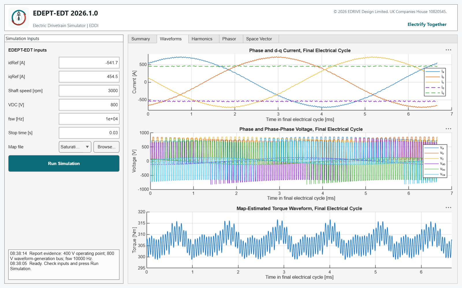
Define the case, run the switching simulation and examine summary, waveforms, harmonics, phasor and space-vector evidence in one interface.
Inspect final-cycle phase and dq currents with requested and achieved operating-point measures.
Apply the switching frequency entered in the interface and compare ripple and harmonic distribution.
Review a linear-order spectrum and current THD through all resolvable orders up to order 200.
Study phase and phase-to-phase inverter voltage behaviour and voltage-demand trends.
Connect phasor and alpha-beta views using the logged absolute electrical rotor angle.
Retain a text diagnostic containing active inputs, map identity and selected outputs.
EXAMPLE SIMULATION OUTPUTS
These example plots show how one operating-point study can be interpreted across time-domain waveforms, harmonic content, phasor construction and absolute space-vector behaviour.

Final-cycle phase currents and their rotating-frame d-q components reveal tracking, ripple and waveform quality.
View full resolution ↗
The final-cycle torque trace exposes mean torque, switching-related variation and repeating electromagnetic structure.
View full resolution ↗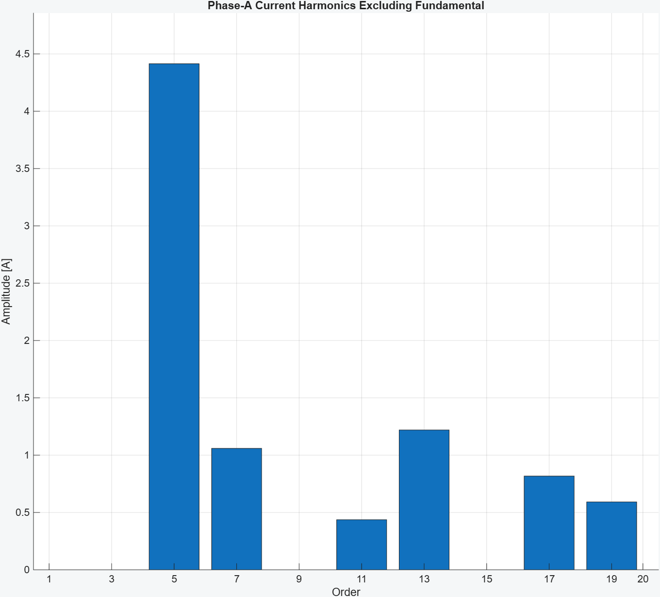
Non-fundamental Phase-A current components make the dominant harmonic orders and their amplitudes directly visible.
View full resolution ↗
Phasor construction connects back-EMF, inductive and resistive contributions to terminal voltage, current and flux linkage.
View full resolution ↗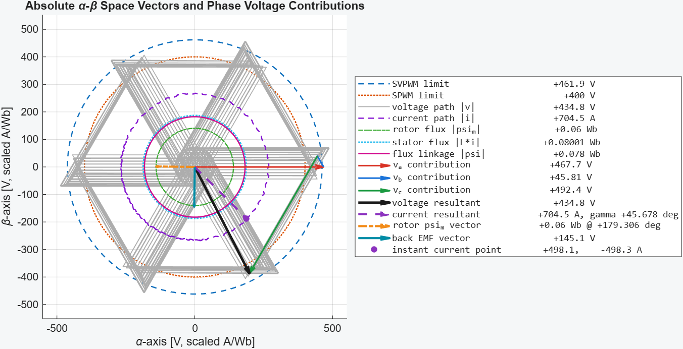
Voltage, current, rotor flux, back-EMF and phase-voltage contributions are resolved against SPWM and SVPWM limits.
View full resolution ↗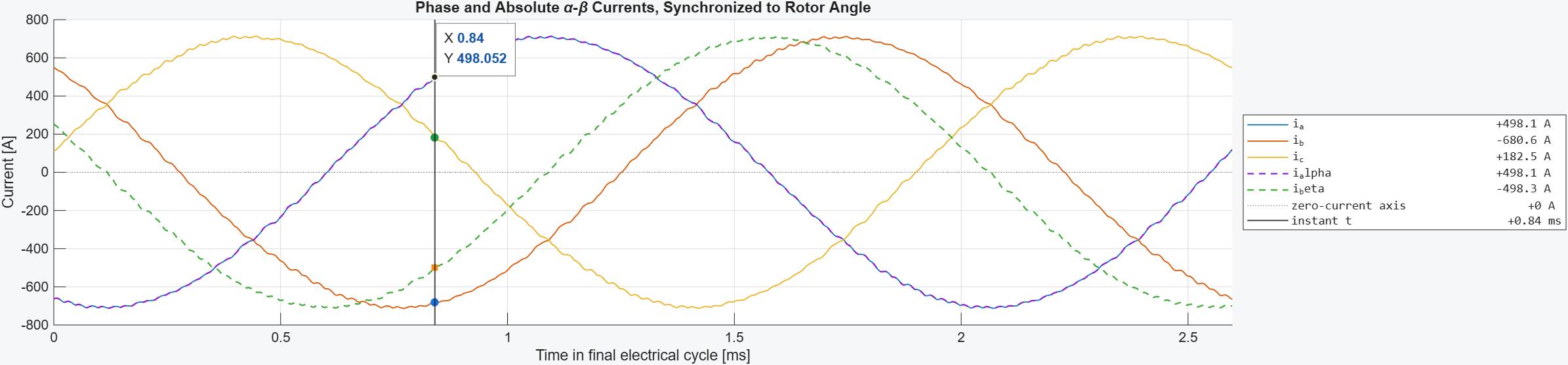
Phase and stationary-frame α-β currents are aligned to absolute rotor angle for time-domain and vector-domain interpretation.
View full resolution ↗Illustrative EDEPT-EDT outputs from a representative simulation. Numerical results depend on the selected e-machine map, operating point, controller settings, voltage assumptions and simulation configuration.
NEW PUBLIC CASE STUDY
A neutral e-machine study covering five operating points from MTPA through field weakening to deep MTPV, simulated in EDEPT-EDT at 6 kHz, 10 kHz and 20 kHz.
Operating points are derived against a 400 V DC bus. An 800 V waveform-generation bus provides controller headroom for the switching-frequency comparison and is not presented as physical inverter feasibility.
Read the 18-page case study ↗DIRECT WORKFLOW
APPROPRIATE USE
EDEPT-EDT is an engineering investigation and comparison tool. Results depend on the supplied map, model assumptions, solver configuration and operating point. The 2026.1.0 release is not a safety-critical or certification-grade design authority and does not claim universal loss, thermal, durability or vehicle-range accuracy.
START THE ENGINEERING WORKFLOW
Evaluate for 14 days with no payment and no automatic conversion, or review the initial charge, renewal date and later recurring price before subscribing.
Request 14-day free trial ↗